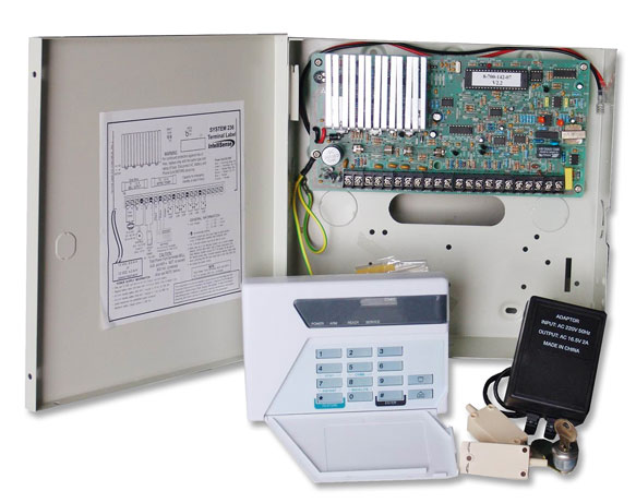
This system adopts MCU control and SMD technology. It can connect 64 channels smoke/heat detectors. Use LED numeral to display alarm address, it can dial automatically alarming to appointed communication device (telephone, hand call) and has speech alarm function. In time inform you fire danger and decrease your loss to minimum. It applies in hotel, marketplace, factory warehouse etc.
10. All smoke/heat detectors are two-wire parallel connected to controller.
ALERT MEMORY display window ---alternately display the channels of all detectors abnormal/ trouble/ alarming 
Installing
- Unlock and open the front cover;
- On installing position mark the installing hole.
- Place the unit on safe position avoiding other object in it. And bore hole according to the mark.
- Strike dilatants into hole;
- Aiming at hole on installing position and tighten screws to fix the back front.
- According to connection-line method and connect line;
- Close front cover and lock it.
Connection-line method(like following fig)
- "DISPLAY/DATA/OUT" jack-----connect display device. The device displays same with panel of controller.
- " TEL IN" telephone jack-----the controller has two telephone jacks. And the controller is parallel connected on telephone line, at first there should be a workable telephone line path. NOTE: When controller don't connect with telephone line, if slide the alarm switch to A, the controller will give "DiDiDi" sound every 20sec, if slide it to B, the alarm is off.
3. "+ALARM OUT–"terminal-----connect alarm light, output power DC12V, current 800mA.
4. "GND+12V +36" terminal-----connect 3-group 12V(>20A/h) storage batteries. During AC power is on, storage battery will be charged automatically. When AC power cut off, the product works entirely by storage battery.
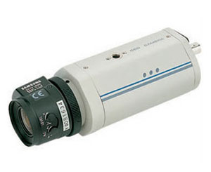
5. "R + "terminal ----- connect DC30V smoke/heat detector. Max.64PCS can be connected. The connection line length is 2400m, adopting red and black wire(at least:18AWG-1015-600V-105℃).
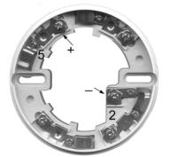 6. Smoke detector base connection wire method:
loosen the screws arrow pointing in the right figure and twine the line head on the screw thread under gasket. And then tighten up the screws. Operation
- Switch on power, CHECK LED light, the system starts checking. After checking, the NORMAL LED light, and simultaneously CURRENT ALAERT window display normal channel number. And then WAITING LED light and system enter waiting state.
- Operate keypad: press and hold "*"key until ALERT MEMORY window display "-" and loose it.
Save telephone number: save A group number: A123456#
save B group number: B4561223#
save C group number: C456789#
save D group number: D789101#
After a group number saved. ALERT MEMORY window display once the group number. (NOTE: when no number is saved in, the dialer will give "Di Di Di Di "sound every 20sec.
delete number: Delete A group number: A#
Delete B group number: B#
Delete C group number: C#
Delete D group number: D#
When number is deleted and you will hear "Di" sound.
record: Press and hold REC key until the sideward LED light, start to record. Record time default is 5sec. If you press and hold REC key to record all the while, the time is 30sec. when recording finish you will hear "DI" sound and then it play automatically.
Play: Press PLAY key, play recorded content.
Reset: Press RES key, the system restart checking to enter waiting state. Pressing the key can also intermit dialing and alarming.
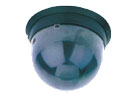
- Trigger smoke detector to alarm:
Attract dry reed tube in smoke detector with magnet (like right fig.), detector's LED flash quickly and then the controller alarm, ALARM LED light, CURRENT ALAERT window flashing display the detector's channel, and ALERT MEMORY window alternately display the channels of all alarming detectors.
- Speech alarm and long-distance intermit dialing:
When controller alarm it automatically alternately dials pre-saved numbers (before it dial certain group number, ALERT MEMORY window display once the group number). Pick up the telephone, and you will hear the recorded speech. If you want to intermit its dialing, at speech stop you can press any key on the telephone. Otherwise after you ring off, the controller will dial the telephone number again.
Every some time controller will check whether smoke detector is abnormal (like: it is stolen) or not. The time interval for check can be set by 4-bit DIP switch (like following figure).when check it abnormal, ABNORMAL LED light, CURRENT ALERT window display the channel of current abnormal detector, ALERT MEMORY window display alternately the channels of all abnormal detectors.
When smoke detector has trouble (for example: it is bad), detector will output a signal to controller and TROUBLE LED light, CURRENT ALAERT window flashing display the channel of current detector hazing trouble, and ALERT MEMORY window alternately display the channels of all trouble detectors.
Coding method
DSW928 smoke detector can be identified by channel code; by 6-bit coding switch its channel code has 64 coding methods (detail in following table).
|
Coding
|
Channel
|
Coding
|
Channel
|
Coding
|
Channel
|
Coding
|
Channel
|
|
000000
|
0
|
010000
|
16
|
100000
|
32
|
110000
|
48
|
|
000001
|
1
|
010001
|
17
|
100001
|
33
|
110001
|
49
|
|
000010
|
2
|
010010
|
18
|
100010
|
34
|
110010
|
50
|
|
000011
|
3
|
010011
|
19
|
100011
|
35
|
110011
|
51
|
|
000100
|
4
|
010100
|
20
|
100100
|
36
|
110100
|
52
|
|
000101
|
5
|
010101
|
21
|
100101
|
37
|
110101
|
53
|
|
000110
|
6
|
010110
|
22
|
100110
|
38
|
110110
|
54
|
|
000111
|
7
|
010111
|
23
|
100111
|
39
|
110111
|
55
|
|
001000
|
8
|
011000
|
24
|
101000
|
40
|
111000
|
56
|
|
001001
|
9
|
011001
|
25
|
101001
|
41
|
111001
|
57
|
|
001010
|
10
|
011010
|
26
|
101010
|
42
|
111010
|
58
|
|
001011
|
11
|
011011
|
27
|
101011
|
43
|
111011
|
59
|
|
001100
|
12
|
011100
|
28
|
101100
|
44
|
111100
|
60
|
|
001101
|
13
|
011101
|
29
|
101101
|
45
|
111101
|
61
|
|
001110
|
14
|
011110
|
30
|
101110
|
46
|
111110
|
62
|
|
001111
|
15
|
011111
|
31
|
101111
|
47
|
111111
|
63
|


 Summary