Smoke alarm control system
Summary
1. channel indicate: when detector working, general controller alarm and corresponding channel LED should light.
2. low-voltage indicate: when standby power is below set value, cut off out power, you can see Low-battery LED flashing and remind you to replace battery in time.
3. tamper protection: when front cover is opened, general controller will give alarm, the 8 LEDs on the left and? right all flash.
4. two remote controllers:
- single-key doorbell remote controller: power voltage DC12V, it can be installed out of the door and used as remote control doorbell;
- 4-key remote controller: power voltage DC12V, it is used for panic alarm, time-delay fortify, quick fortify, cancel.
5. fortify: when host leave home, use remote controller to set general controller on fortify state, when someone enter its detection field, general controller will give alarm (>90db), if connect dial number implement of our company, general controller will also give alarm weft, for example 110 or your home’s telephone.
6. cancel: after host come back home and cancel the general controller’s fortify state, when host enter detection field, the general controller will not alarm.
7. panic alarm: when danger occur in your home, you can prees the panic key to give panic asking for help signal to neighbor or others and obtain other’s help.
8. alarm memory: on fortify state, when host isn't at home there is person enter detection field, general controller alarm, after the alarm stops, the corresponding LED still light to indicate that channel ever had danger, only after using remote controller to reset, the LED will be off.
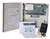
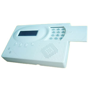
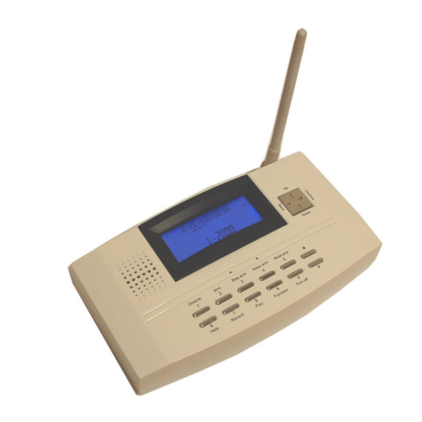
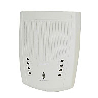
GENERAL CONTROLLER
1.Connection-wire figure:
- terminal 1&2: output voltage, connect 1 with "-",connect 2 with "+";
- terminal 3&4 can connect with wire detector, is 5th channel CN5, corresponding indicator is Ch5;
- terminal 5&6 can connect with wire detector, is 6th channel CN6, corresponding indicator is Ch6;
 terminal 7&8: alarm output, when it alarm, other alarm connected with it also alarm,7connect with "-", 8 with "+"; terminal 7&8: alarm output, when it alarm, other alarm connected with it also alarm,7connect with "-", 8 with "+"; - terminal 9&10: other output;
- terminal 11&12 input voltage , connect 11 with "-", connect 12 with "+".
2.operation
2.1 install detector on selected position;
2.2 connect wire according to connection-wire figure: connect "-" and "+" of power adapter to terminal 11&12, and the polarity can not be connected oppositely, connect CN5 and CN6 with wire detector, they are two wire channels, the? correspondinng indicator separately is Ch5 and Ch6, NOTE: if CN5 or CN6 is not connected, general controller will alarm and corresponding channel LED (Ch5 or Ch6) will light, so when no wire detector connected, CN5 and CN6 shoud be short connected avoiding unwanted alarm;
2.3 install 6 AA batteries into battery container according to right polarity;
2.4 plug power adapter into power socket, power LED should light, Fortify and Low-battery LEDs flash once 0.5 second, after 60s, general controller give one DI sound, Fortify LED flashes once 2s and Low-batter4y LED stop flashing and remain on. NOTE: during this 60s, any operation is not effect.
- close front cover. NOTE: after power is on, there is 60s to wait you close front cover avoiding tamper alarm.
2.6 press the panic key on general controller, it give panic alarm and all LEDs light, the alarm time is 3Min 30s(press the cancel key on 4-key remote controller to stop alarming quickly);
- press fortify key on 4-key remote controller, set general controller on fortify state;
- ?test every detector one by one, when wire detector work, general controller alarm, the alarm time is 3Min 30s, the corresponding channel LED(Ch5 or Ch6)should light. When wireless detector work, general controller should alarm, alarm time is 3Min 30s, corresponding channel LED(Ch1 or Ch2,3,4,5,6)should light.
- attention:
- avoid installing the unit on metal base;
- when general controller alarming, the sound is very high, so when alarm occur, you should eliminate it in time avoiding affecting others.
- if power adapter need replacing, the replacing adapter's standard should be: input voltage 110VAC/230VAC, output voltage 10~12V/DC, current 1A. suggest you contacts with supplier and use original adapter.?
- if the power adapter is connected oppositely, the unit will not work, but it will not be damaged;
  the connection line between wire detector and general controller should not exceed 3m, and should install detector out of the way.? the connection line between wire detector and general controller should not exceed 3m, and should install detector out of the way.?
 DOORBELL REMOTE CONTROLLER DOORBELL REMOTE CONTROLLER
1. operation: install it out of the door and use it as remote control doorbell, press the key, general controller will give Dingdong Dingdong to remind host open door. It can not operate other function of the general controller.
2.Attention: avoid installing the unit on metal base.
Basis configuration
Main controller(1PCS),smoke detector DSW928(32PCS)
Option unit
Heat detector,alarm light,display device!
4-KEY REMOTE CONTROLLER
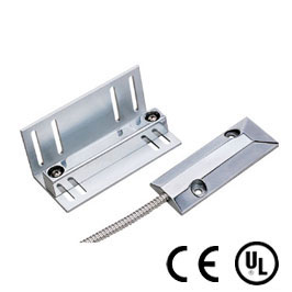
DOOR MAGNETISM
1.install magnetism and emitter on upright position of door lock, the distance between them is 3mm~5mm and triangle on emitter aim at triangle on magnetism(like right figure);
2. install DC12V battery into emitter;
3. press fortify key on 4-key remote controller, set general controller on fortify state;
- Open door, the emitter is triggered and its LED light, then emit signal to general controller, the general controller alarm, provided that its corresponding channel is channel 5, the Ch5 should light.
- Tamper design: Under the condition that the triangle on emitter aim at triangle on magnetism, when emitter’s battery lid is removed, it will emit signal and its LED light.
- Attention: the magnetism should be on the left of the emitter(like following figure).
THE SYSTEM CONFIGURATION
| Basic configuration |
 |
 |
 |
 |
 |
| General controller*1 |
doorbell remote controller*1 |
4-key remote controller*1 |
DPS-55 PIR detector*1 |
door magnetism*1 |
| The units for your choosing at will |
 |
 |
 |
 |
|
| glass-break detector |
695 PIR detector |
DDT-15 glass-break& PIR detector |
double detector |
|
| |
 |
 |
 |
|
|
| DSW-98A Smoke detector |
Smoke detector |
PIR detector |
|
|
|


 PDFSize:Byte

 Model: EMC 958Magnetic Contact
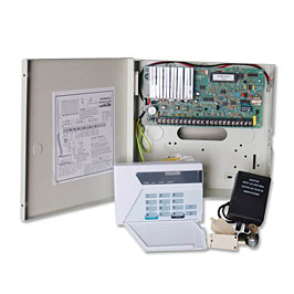 Model: BAS-238CPControl Panels
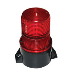 Model: ESB-122HStrobe Beacon